
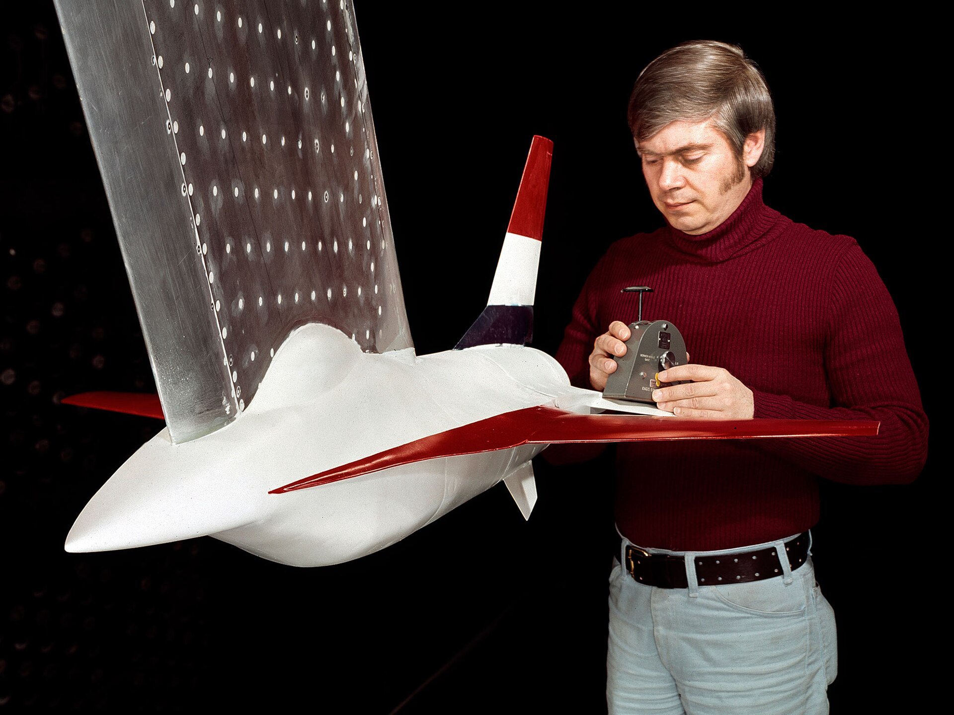
Aerodynamic modelling flight dynamics aircraft work translates forces and moments into a model that predicts motion. The model connects geometry, airflow, mass properties, controls, propulsion, and atmosphere so engineers can evaluate stability, handling, performance, and control laws.
No single method supplies the whole answer. Analytical estimates, computational fluid dynamics, wind-tunnel tests, and flight data contribute at different stages and levels of fidelity.
Aerodynamic Modelling Flight Dynamics Aircraft Framework
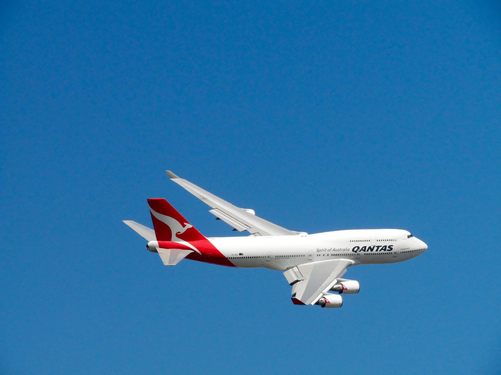
A flight-dynamics model resolves forces and moments along the aircraft axes. Lift, drag, side force, rolling moment, pitching moment, and yawing moment vary with angle of attack, sideslip, control deflection, rate, Mach number, Reynolds number, and configuration.
Engineers often express these relationships through nondimensional coefficients. This makes data easier to compare across scale, speed, and test method.
The model also includes mass, inertia, center of gravity, propulsion, landing gear, and environmental effects. Aerodynamics alone cannot predict complete motion.
Start with the Mission and Flight Envelope
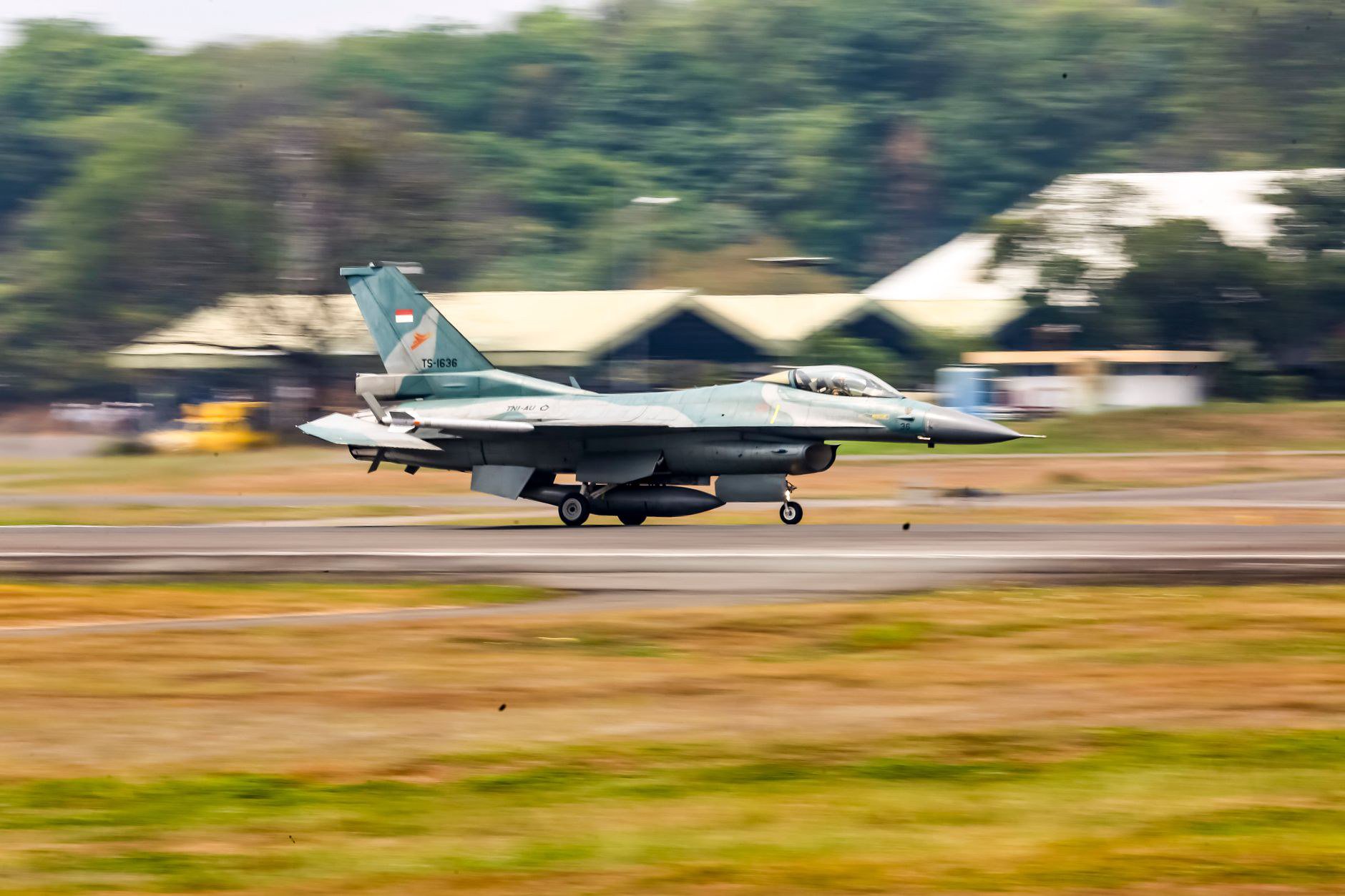
A transport, trainer, eVTOL vehicle, and hypersonic demonstrator require different emphasis. Define speed, altitude, configuration, maneuver, payload, and environmental ranges before choosing model fidelity.
Early conceptual work may use empirical methods and low-order tools. Detailed design adds CFD, tunnel testing, and subsystem models. Certification and control-law development demand traceable validated data.
Emerging configurations in our urban air mobility coverage show why hover-to-cruise transitions create modelling challenges beyond conventional fixed-wing envelopes.
Static Stability Derivatives
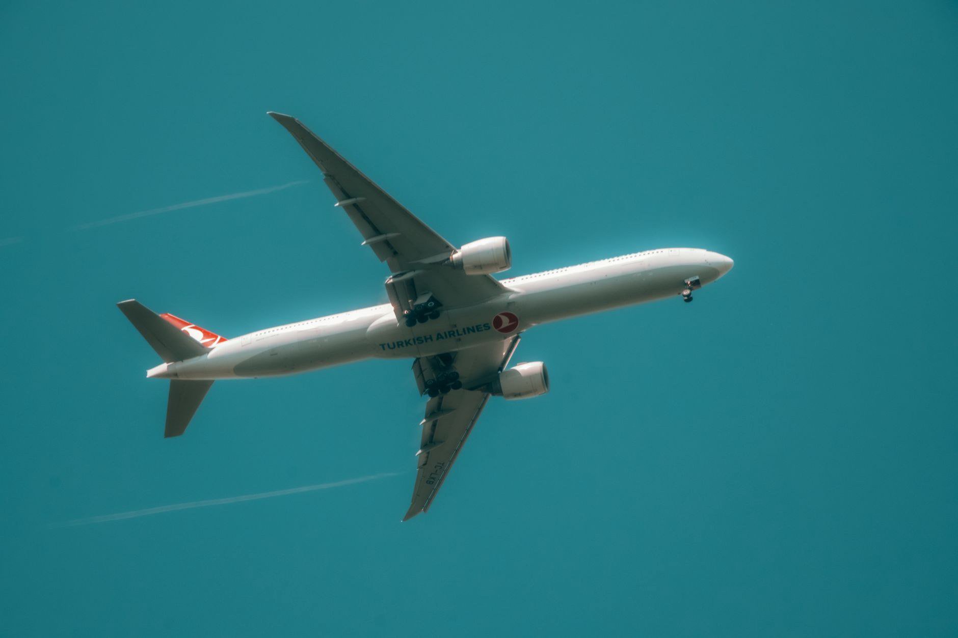
Static derivatives describe how forces and moments change with variables such as angle of attack and sideslip. Pitching-moment slope helps determine longitudinal stability. Side-force, rolling-moment, and yawing-moment derivatives shape lateral-directional behavior.
Control derivatives represent elevator, aileron, rudder, spoiler, flap, or thrust effects. Their values can change substantially with configuration and dynamic pressure.
These derivatives are useful for linear analysis near a trim point. They do not replace nonlinear models at high angle of attack or large control deflection.
Dynamic Derivatives and Unsteady Effects
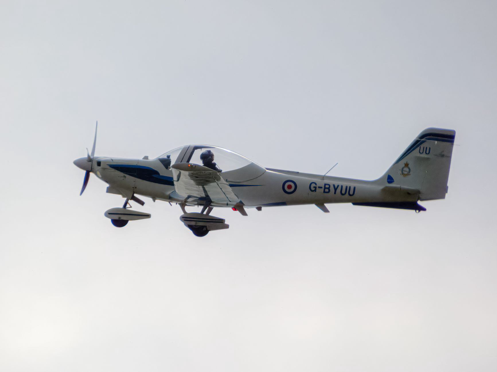
Aircraft response depends on motion as well as instantaneous attitude. Pitch, roll, and yaw rates alter the surrounding flow and generate damping moments.
Dynamic derivatives influence short-period, phugoid, Dutch-roll, roll, and spiral modes. Wind-tunnel oscillation tests, CFD, and system identification can estimate them.
Unsteady aerodynamics become important in rapid maneuvers, flexible structures, rotor interactions, gusts, and separated flow. Model complexity should match the decision being made.
Computational Fluid Dynamics
CFD resolves airflow around geometry at a chosen level of approximation. It provides pressure, shear, flow-field, and integrated force data across conditions difficult to test physically.
Mesh quality, turbulence modelling, boundary conditions, transition assumptions, and convergence all affect results. A colorful flow image is not validation.
Engineers compare CFD against known cases, tunnel measurements, and later flight data. Disagreement should be investigated rather than hidden by curve fitting.
Wind-Tunnel Testing
Wind tunnels provide controlled measurements and physical evidence. Balance systems measure forces and moments, while pressure taps and flow visualization reveal local behavior.
Scale introduces Reynolds-number and support-interference questions. Wall effects, model deformation, and transition devices need correction or accounting.
Tunnel data can populate coefficient tables and validate computational trends. Tests are most useful when designed around clear model uncertainties.
Propulsion-Airframe Interaction
Propellers, rotors, jets, and inlets change local flow. Thrust may alter tail effectiveness, wing lift, control response, and trim. The interaction can vary with power setting and speed.
For distributed propulsion or vertical lift, simple thrust addition may be insufficient. Wake geometry and transient effects can dominate parts of the envelope.
Broader propulsion challenges are examined in our analysis of advanced propulsion systems.
From Coefficients to Simulation
A nonlinear simulation interpolates aerodynamic data, calculates forces and moments, and integrates the equations of motion. It may include actuators, sensors, control computers, atmosphere, and pilot inputs.
Interpolation must behave sensibly between test points and at table boundaries. Abrupt gradients can create numerical artifacts or false handling qualities.
Real-time simulators may use simplified models with known fidelity. Engineering analysis can accept slower, higher-detail computation when timing is not operationally constrained.
Trim and Linearization
Trim solves for a steady condition where forces and moments balance. Engineers trim across altitude, speed, weight, center of gravity, and configuration.
Linearization around each trim point supports stability analysis and control design. Eigenvalues and mode shapes reveal damping and frequency.
Results should be checked against nonlinear simulation. A linear model is local; large maneuvers can leave its valid region quickly.
Model Validation with Flight Test
Flight testing provides the final evidence of aircraft behavior. Carefully designed maneuvers excite specific modes or derivatives while instrumentation records controls, motion, air data, loads, and propulsion state.
System identification estimates model parameters from measured response. Engineers compare predictions with data, update uncertain terms, and preserve the rationale for changes.
Flight data contains sensor bias, atmospheric disturbance, structural response, and pilot-input uncertainty. Validation needs disciplined processing.
Manufacturing and Configuration Control
The aircraft that flies must match the geometry and mass properties represented in the model. Surface tolerances, gaps, rigging, deformation, and center-of-gravity variation influence behavior.
Precision production practices connect aerodynamic intent with hardware. Our coverage of engineering and machining shows the manufacturing context behind validated designs.
External performance perspectives from Lakeland FC concern a different field, but they similarly illustrate the value of measurement, repeatable methods, and feedback when refining complex performance.
Uncertainty Must Remain Visible
Models should carry confidence ranges and known limitations. Sparse high-angle data, uncertain transition, configuration gaps, and scale corrections should be documented.
Safety analysis can then test worst-case parameter combinations. Control laws can be evaluated against dispersions rather than one nominal aircraft.
Aerodynamic modelling flight dynamics aircraft design succeeds when assumptions, data sources, validation, and uncertainty stay connected. The model is not the aircraft; it is an engineering argument that must improve as evidence accumulates.