
When a thin aerospace wall shows wavy marks or lets out a high-pitched squeal during cutting, the process is almost certainly chattering. Fixing chatter in 5-axis machining of thin-wall parts starts with one idea: chatter is a self-sustaining vibration between the cutter and the wall. It usually signals a stability problem rather than a bad tool. Three levers resolve most cases: spindle speed, depth of cut, and how the part is held. Check them in that order before touching the toolpath, because reprogramming first often hides the real cause.
Read the Symptoms Before You Change Anything
Chatter leaves a recognizable signature, and reading it correctly saves hours of guesswork. A stable cut sounds steady and leaves a clean surface. An unstable one seems to fight itself. Start by inspecting the wall under good light, then listen to the machine while it runs.
Surface marks that repeat in a regular wave usually point to a speed problem. The tool lands in nearly the same spot on each revolution and reinforces the vibration. Random scatter across the surface suggests the wall itself is moving, which hints at weak support or clamping. The two patterns look alike at a glance, so check before deciding on a fix.
An audible squeal, or a sudden change in pitch, means the process has tipped into instability. Operators often hear it before they see any mark. Dimensional drift is the quietest warning. A wall may measure correctly near the top but drift off lower down, where it is longest and thinnest. That pattern often means the cut is stable at the start and unstable deeper in the pass.
Stability Lobes and Finding Safe Speeds
Stability lobes work like a map. For a given tool, holder and engagement, the map shows which spindle speed and depth-of-cut combinations stay quiet. Picture a set of safe islands surrounded by chatter. The peaks of those islands are where you want to run.
A full lobe diagram is rarely necessary to get useful results. A simple test works well. Hold the depth constant, sweep the spindle speed across a range, and listen for quiet zones while watching the surface. Mark the stable pockets once you find them. Test passes on scrap cost far less than a ruined part, and the data carries over to later runs of the same geometry.
Once you find a stable pocket, move your speed toward its peak rather than guessing inside the chatter zone. Running at the edge of a lobe is risky. A small change in tool wear or stick-out can push the process back into instability. Centering on the peak leaves room to absorb ordinary variations.
Why Tool Stick-Out and Holder Choice Matter
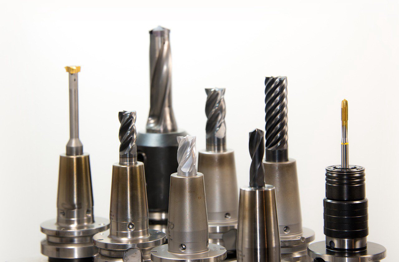
Stick-out is the length of tool that projects past the holder. Each extra unit of length lets the tool bend more under load, and stiffness drops quickly as reach grows. A tool that runs quietly at one length can start chattering after a modest increase in reach, which is why stick-out is one of the first things to check.
Reducing stick-out is one of the most direct stability levers available, and the effect should be verified on your own machine rather than assumed. The holder matters as much as the length. Shrink-fit and hydraulic holders grip the shank more rigidly than a standard collet, which is why they tend to perform better on finishing passes in thin walls. A shorter flute with a stiffer shank often outperforms a longer reach tool, even when the longer tool seems to solve an access problem. Access is a real constraint, but forcing a long tool into it usually costs more in scrap than a second setup would.
Fixturing and Internal Support for Thin Walls
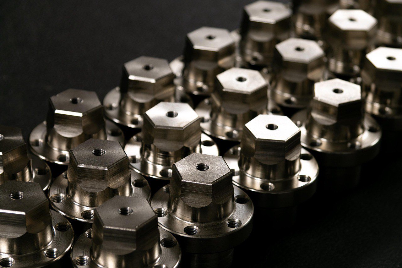
A thin wall needs support from the inside, not only clamping from the outside. Clamping holds the part in place, but it does little to stop the wall from flexing under the cutter. Without internal support, the wall behaves like a diving board, and a diving board wants to vibrate.
Sacrificial support material or a backing fixture raises local stiffness right where the tool is working. Clamp load needs the same care. Too much force deforms the thin wall, so it springs out of tolerance once released. Too little lets the part shift and vibrate. The target is enough force to hold the part still without bending it, and that balance usually takes a few trial clamps to find.
Sequencing Step-Downs and Machining Order
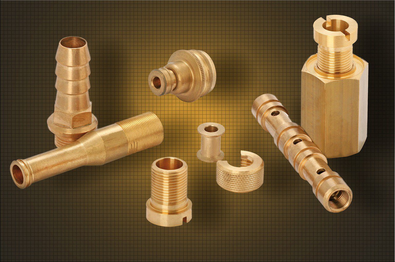
The order of material removal decides how stiff the wall stays during the cut. If you cut one side deep and leave a thin, unsupported section standing alone, that section becomes a long cantilever, and chatter follows quickly. Balanced passes keep the wall supported from both sides as the job progresses.
Where possible, leave the thinnest section for last and finish it with a light pass. By then most of the surrounding material is gone, so the thin area carries less load. On double-walled features, alternate sides between passes. That keeps stiffness even and stops one wall from drifting while the other is being cut.
Variable-Pitch and Variable-Helix Cutters

Chatter feeds on itself through regeneration, since each flute cuts into the wave left by the one before it. Uneven flute spacing breaks that rhythm. The waves stop lining up, and the vibration has nothing consistent to build on. This is why variable-pitch and variable-helix cutters can widen the stable speed range.
Variable-pitch end mills help most on thin, long engagements, where the regenerative effect is strongest. They are not a universal fix. Confirm that the cutter geometry suits both the material and the engagement you actually run. A cutter designed for aluminum can behave poorly in titanium, and a tool suited to light finishing may struggle under heavier roughing. Test before committing to a full production run.
Is the Fixture or the Tool the Real Cause?
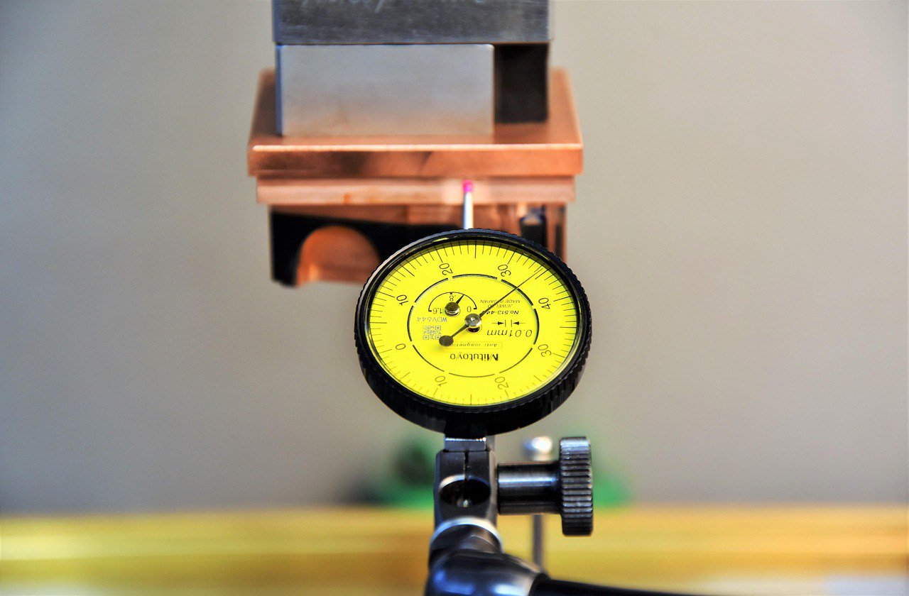
This is the question engineers ask most often. A practical way to separate the two is to change one thing at a time. If chatter disappears when you shorten the tool, the holder or stick-out was the culprit. If it persists until you add internal support, the wall was moving and the tool was not at fault. Changing several variables at once hides the real cause and wastes machine time.
A Symptom-to-Fix Reference for the Shop Floor
Use the following reference as a first pass when a problem appears. Each entry pairs what you see with the most likely cause and the first step to try. It should guide your initial checks rather than replace them.
| Symptom | Likely cause | First fix |
|---|---|---|
| Regular wave marks on wall | Speed inside a lobe | Shift spindle speed to a lobe peak |
| Chatter only at full depth | Excess axial engagement | Reduce depth of cut, take more passes |
| Wall moves under the tool | Weak support or clamp | Add backing support, adjust clamp force |
| Chatter after tool change | Excess stick-out | Shorten reach, switch to shrink-fit holder |
| Marks despite stable speed | Unbalanced engagement | Use variable-pitch cutter, rebalance passes |
Verifying Parameters on Your Own Setup
Stability thresholds depend on the machine, holder, alloy and tool geometry, so no general figure transfers reliably from one shop to another. Establish your own baseline with a controlled stability test on representative stock. Record the stable speed and depth combinations you find, then use them as the starting point for production programming.
Our Multi-Axis Approach to Aerospace Thin Walls
Machining strategy and tool selection work best when you plan them together. A toolpath that looks flawless on screen can still chatter if the holder and fixture were chosen without it in mind. Process planning should be treated as one integrated decision. Many clients reach out through monacloud.vn when they need a partner who can review the whole setup rather than only the program.
Turbine-type geometry with tight wall tolerances needs even closer attention to tooling. Stability margins are narrower there, and the cost of a scrapped part is high. Those jobs benefit from reviewing cutter and holder choices before the first cut, and from a short stability test on representative stock.
For readers building out their broader manufacturing knowledge, our guide to 5-axis CNC machining for aerospace components covers the wider process context, and our notes on precision tooling for multi-axis machining of turbine components go deeper on cutter and holder selection for tight-tolerance geometry. Our piece on titanium alloys in aerospace machining is also useful when your thin walls are titanium.
Frequently Asked Questions
Can I fix chatter just by changing the spindle speed?
Sometimes, yes. When the marks follow a regular wave pattern and the chatter appears at a specific speed, shifting to a lobe peak often solves it. If the wall itself is moving, though, speed alone will not stop the vibration. Check support and stick-out before assuming speed is the only lever to pull.
Is a variable-pitch cutter always better for thin walls?
No. Variable-pitch cutters break up the regenerative effect and can widen the stable range, which helps on thin, long engagements. They are not a universal solution, and the cutter must match your material and engagement. Test it on representative parts before relying on it in production.
How do I know if the fixture or the tool is the real cause?
Change one variable at a time. Shorten the tool and watch whether the chatter drops, then add internal support and see whether the behavior changes. The factor that makes the difference is usually the real cause. Changing several things together hides the answer and costs time on the shop floor.